Quality work with Metal additive manufacturing requires attention to detail, and experience. Farsoon is happy to share with you a few quick guidelines in 3D printing design that will help improve the printing quality and success rate.
1. Optimized Design of Parts
There are two characteristics of the metal 3D printing process: stair stepping during inclined surfaces and the need for support. Supports play a role in heat transfer, preventing deformation of the part, as well as stabilizing the part. Supports will need to be removed manually after printing. Characteristics that should be considered during the additive design process include avoiding excessive stress, avoiding large horizontal overhangs, increasing angles of self-supported features, and upside-down rounded corner transitions, etc.
(1) Optimization of large horizontal overhang
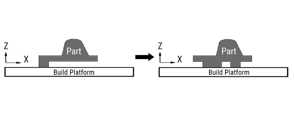
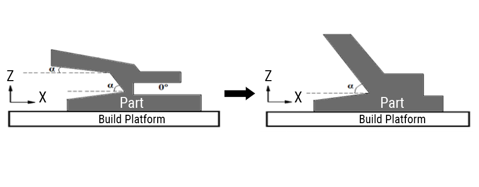
(2) Increasing the angle of incline to reduce the step effect and achieve self-supporting
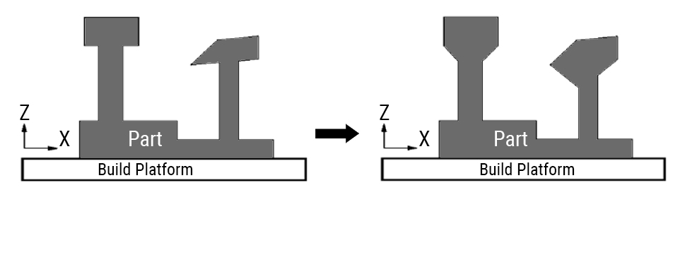
(3) Self-support designs
2. Part Layout
The part orientation of the build plate has a big impact on the quality. Certain orientations can achieve minimal support structure. Consider the following when placing the part:
• Ease of powder removal
• Minimize support coverage
• Minimize print time
• Orient the part to ensure the best quality of important features
• Minimize post-processing
3. Support Design
After optimizing the design and adjusting the orientation of the parts, the following factors need to be considered when using the support structure:
• Type of support
• Strength of the support
• Ease of part removal
• Ease of powder removal
4. Build Layout
By optimizing the layout of the parts on the build platform, you can reduce print failures.
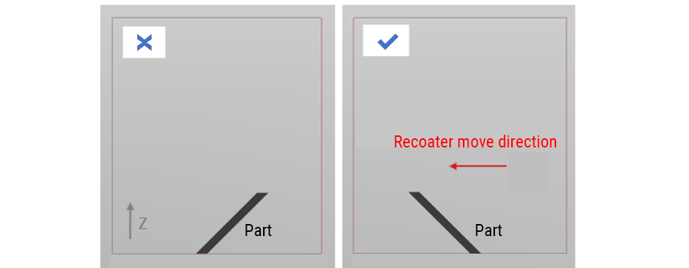
(1) When the sintering direction of the suspended part is opposite to the movement direction of the recoater, the friction between the scraper and the contour of the part will exacerbate the warping of the edge of the workpiece, leading to an increased risk of printing failure. If it cannot be prevented, even when the incline angle of the suspension part is greater than the critical suspension angle, support should be added to reduce the printing risk.
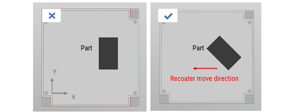
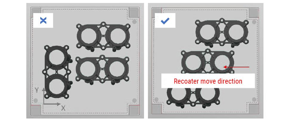
(2) Avoid placing the part parallel with the recoater, rotate the part in the Z axis to minimize impact force with the recoater on the part. Deformation typically occurs around the edges and corners of the part. By rotating the part in the Z axis, the protrusion edge contacts the recoater gradually rather than all at once, thus retaining the quality of small features.
(3) Avoid placing the parts in the direction of the recoater’s movement direction. If a collides happened, causing damage for the part and the recoater, there is still a chance that the build can continue. Farsoon’s Buildstar software offers a real-time part deletion feature. The operator can delete the damaged part while continuing to print undamaged parts. When part collisions with the rocoater occur, the collision will cause uneven powder distribution in the front and the back of the part, rendering the area unusable. Therefore, it’s recommended to avoid placing parts in front or behind high-risk parts.
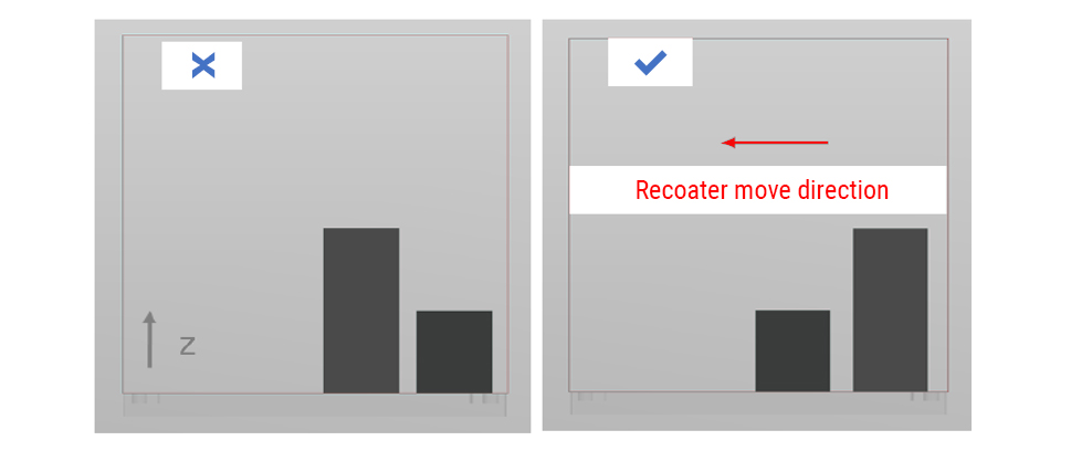
(4) Place the workpiece with a greater build height closer to the powder feed side. Generally, the quality of the powder bed near the powder feed side tends to be better. After finishing the shorter part, having the larger part closer to the feed side will reduce the amount of powder needed, thus avoiding the need to refill additional powder during the build.
Farsoon Technologies has a professional technical team that supports the development of customer applications in all aspects from equipment, software, technology, and design. Contact us for any questions you have: globalinfo@farsoon.com.